Wireless UART via infrared
V. Hunter Adams
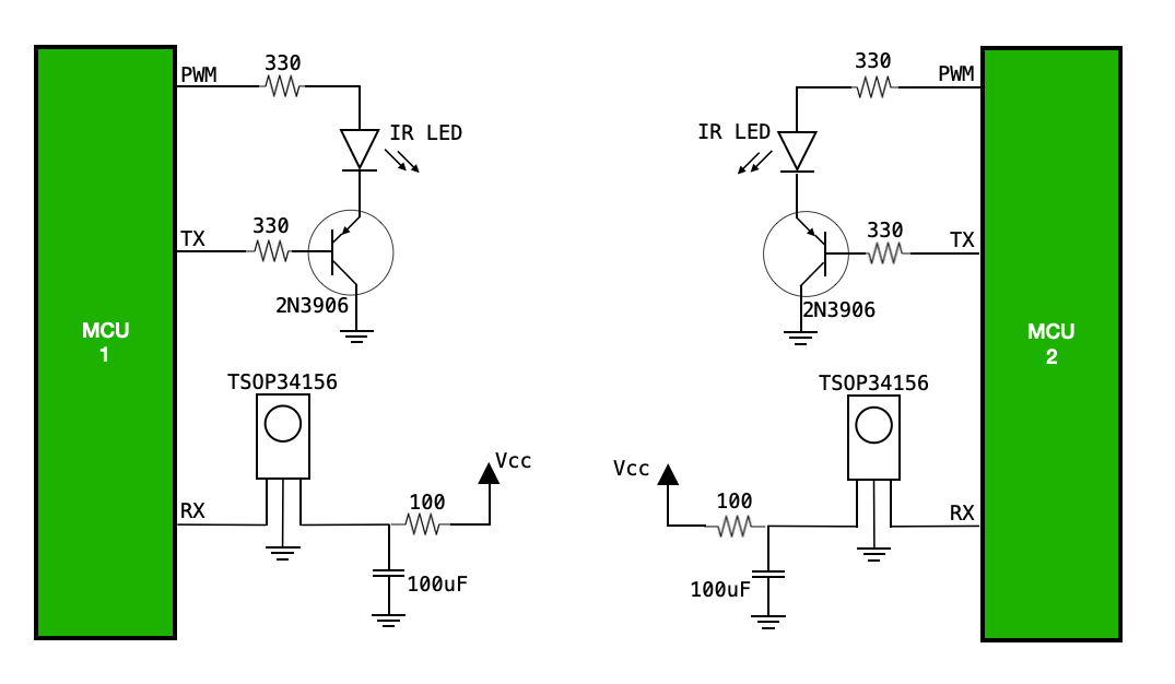
For short-range wireless communication, infrared can be really handy. This webpage describes how to build a wireless infrared serial link between two microcontrollers using a TSOP34156 IR receiver module, an infrared LED, and a PNP transistor.
The Circuit
Understanding the circuit
The infrared receiver/demodulator
The TSOP34156 demodulates bursts of 56kHz infrared light. In order for this demodulation to occur without error, those bursts need to generated according to the specifications described in the table at the bottom of page 5 of the datasheet. These specifications relate to the number of cycles per burst, the gap time between bursts, and the maximum number of continuous burst per second. If the bursts are generated according to these specifications, the automatic gain control in the receiver does a good job rejecting noise.
If we drive an IR LED from a 56kHz PWM channel and use a 4800 baud UART TX line to (effectively) modulate that PWM channel on/off, then we end up with a number of cycles per burst that is about right for the TSOP34156. In particular, we get 11-12 cycles per bit. If we allow for a short gap between characters, the error rate over short transmission distances is very low (but not zero). I haven't run a full statistical test, but it seems to lose 1 bit every 10,000 or so. For applications in which any bit error is not permissable (e.g. a serial bootloader), checksums and handshakes detect errors and request retransmissions. An RC lowpass filter has been added, per the datasheet, to reduce supply ripple.
Note that the output signal goes low when the receiver detects IR flashing at 56kHz. This signal attaches directly to the UART RX input. So, we need for the transmitter to generate 51kHz cycles when the UART TX line is high and to stop generating pulses (which makes the receiver signal go high) when the UART TX line is low. A PNP transistor facilitates this.
The infrared LED
The IR LED is constantly driven by a 56kHz PWM output. The low-side of the LED connects to the emitter of a PNP transistor, the base of which is driven by the UART TX line and the collector of which connects to ground. This way, current flows through the LED when the TX line is low, and it does not flow through the LED when the TX line is high. This inverts the TX signals. The UART TX line idles high, which turns off the PNP resistor and prevents the IR LED from flashing. As a consequence, the signal line connected to the RX input of the receiving device goes high. When the UART TX signal goes low, the LED is allowed to flash the the signal output of the TSOP34156 goes low. The microcontroller has no idea that there isn't a wired connection between RX and TX.
At present, the IR LED is driven directly from the PWM output. These LED's can take up to 40mA. With one more NPN transistor, you could drive way more current through that LED for longer-distance transmissions.